Asdu transfer: Difference between revisions
No edit summary |
No edit summary |
||
| Line 7: | Line 7: | ||
Here is an example configuration of the IEC101 ports in GWS<br /> | Here is an example configuration of the IEC101 ports in GWS<br /> | ||
[[ | [[Image:Asdu transfer ports.png]] | ||
The uplink (slave channel) is configured to Port4 with link address 100 and ASDU address 100.<br /> | The uplink (slave channel) is configured to Port4 with link address 100 and ASDU address 100.<br /> | ||
| Line 16: | Line 16: | ||
"Devices" configuration for the lower level RTU-s<br /> | "Devices" configuration for the lower level RTU-s<br /> | ||
[[ | [[Image:Asdu transfer devices.jpg]] | ||
*IEC101 traffic of lower level devices is transferred to Port4 uplink. The parameter to configure this is called ASDU transfer in "Devices" tab. For every device, Port4 has been configured as the asdu transfer uplink port in this example.<br /> | *IEC101 traffic of lower level devices is transferred to Port4 uplink. The parameter to configure this is called ASDU transfer in "Devices" tab. For every device, Port4 has been configured as the asdu transfer uplink port in this example.<br /> | ||
Latest revision as of 11:12, 4 June 2019
Asdu transfer is a feature to transfer data from multiple IEC101 master channels to one IEC101 slave channel.
The feature supports both IEC101 unbalanced and IEC101 balanced transmission.
In the slave channel, different devices can be polled from a single IEC101 channel by polling different ASDU-s within the channel.
The link address for all devices will remain as configured in the uplink port (IEC101 slave port). In this example, it is 100
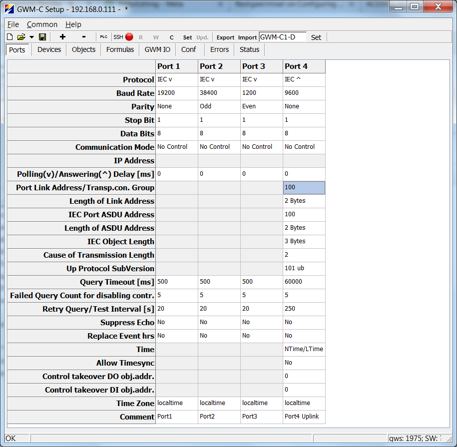
Here is an example configuration of the IEC101 ports in GWS
The uplink (slave channel) is configured to Port4 with link address 100 and ASDU address 100.
For the lower level devices, three ports are configured: Port1, Port2 and Port3.
Note that the lower level devices may have different baudrate, parity etc. It is not necessary for these settings to match parameters of the slave channel.
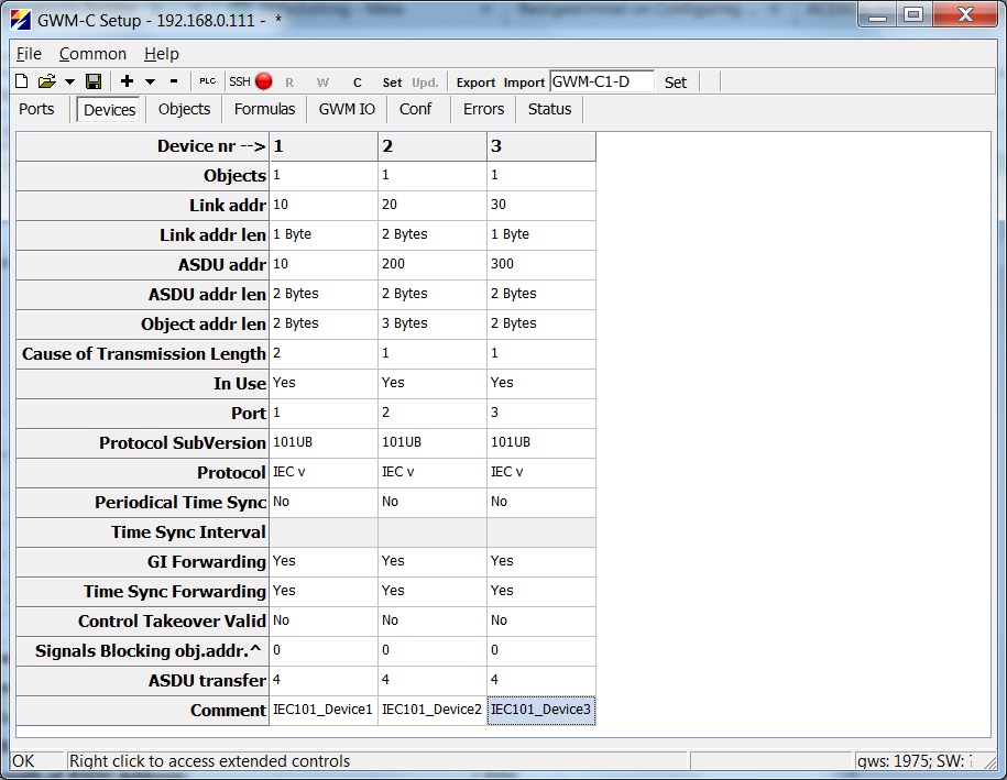
"Devices" configuration for the lower level RTU-s

- IEC101 traffic of lower level devices is transferred to Port4 uplink. The parameter to configure this is called ASDU transfer in "Devices" tab. For every device, Port4 has been configured as the asdu transfer uplink port in this example.
- The ASDU addresses of every device used in the "ASDU transfer" feature must be different.
- No information objects should be configured for devices in the "ASDU transfer" feature. The data is transferred directly without object database.
- The link addresses of configured devices may be different for every device, but it may also be equal for every device.
- Length of link addres, ASDU address, object address and COT may vary. It is not important for these parameters to match the uplink port settings or settings of other lower level devices.
- In this example:
- The controlling station will connect to Port4 using IEC101, link address 100.
- When the controlling station polls for {link address 100; ASDU address 10}, then the query is only forwarded to Port1, because Device1 has ASDU address 10.
- Similarily, when the controlling station polls for {link address 100; ASDU address 300}, then the query is only forwarded to Port3, because Device3 has ASDU address 300.
- When the controlling station polls for {link address 100; ASDU address 100}, then the query is addressed to the Martem RTU itself. The RTU will respond with all the objects configured in the database (all objects in "Objects" tab, plus the physical I/O-s, plus objects from "Formulas")
- The controlling station will connect to Port4 using IEC101, link address 100.
